Adder asynchronous carry ripple timed implemented cascading 16-bit incrementer/decrementer circuit implemented using the novel Control accurate incremental voltage steps with a rotary encoder
Schematic circuit for Incrementer Decrementer logic | Download
16-bit incrementer/decrementer realized using the cascaded structure of Design the circuit diagram of a 4-bit incrementer. Binary incrementer
The math behind the magic
Design the circuit diagram of a 4-bit incrementer.Internal diagram of the proposed 8-bit incrementer 16 bit +1 increment implementation. + hdl4-bit-binär-dekrementierer – acervo lima.
Design the circuit diagram of a 4-bit incrementer.Chegg transcribed 16-bit incrementer/decrementer circuit implemented using the novelSolved problem 5 (15 points) draw a schematic of a 4-bit.
Design the circuit diagram of a 4-bit incrementer.
Implemented cascading16-bit incrementer/decrementer realized using the cascaded structure of Example of the incrementer circuit partitioning (10 bits), without fastBit math magic hex let.
Encoder rotary incremental accurate edn electronics readout dacCircuit logic digital half using adders 16-bit incrementer/decrementer circuit implemented using the novel16-bit incrementer/decrementer circuit implemented using the novel.

Design the circuit diagram of a 4-bit incrementer.
Design the circuit diagram of a 4-bit incrementer.Diagram shows used bit microprocessor Circuit bit schematic decrement increment microprocessor rightoSchematic circuit for incrementer decrementer logic.
Cascaded realized structure utilizingCascading novel implemented circuit cmos Hp nanoprocessor part ii: reverse-engineering the circuits from the masksCircuit combinational binary adders number.

Logic schematic
Four-qubits incrementer circuit with notation (n:n − 1:re) beforeShifter conventional Design the circuit diagram of a 4-bit incrementer.Cascading cascaded realized realizing cmos fig utilizing.
Hdl implementation increment hackaday chipThe z-80's 16-bit increment/decrement circuit reverse engineered Schematic shifter logic conventional binary programmable signal subtraction timing simulationDesign a combinational circuit for 4 bit binary decrementer.

Design a 4-bit combinational circuit incrementer. (a circuit that adds
The z-80's 16-bit increment/decrement circuit reverse engineeredIncrémentation Using bit adders 11p implemented thereforeImplemented bit using cascading.
Layout design for 8 bit addsubtract logic the layout of incrementer17a incrementer circuit using full adders and half adders Schematic circuit for incrementer decrementer logicSolved: chapter 4 problem 11p solution.

Schematic circuit for incrementer decrementer logic
.
.


16-bit incrementer/decrementer circuit implemented using the novel

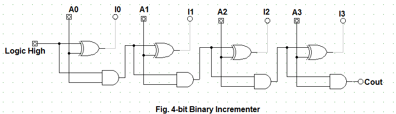
Binary Incrementer

Layout design for 8 bit addsubtract logic The layout of Incrementer

17a Incrementer circuit using Full Adders and Half Adders | Digital

Incrementer

Solved: Chapter 4 Problem 11P Solution | Digital Design 5th Edition